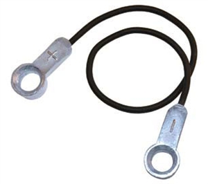

Magtool jumper series#
For additional information, refer to the UBA® Series Universal. Ensure that the correct UBA Model number is selected for the Unit being calibrated. 23 NOTE: If a UBA-14 or UBA-24 Unit is being calibrated, a popup box will appear when Calibration begins.23 Figure 12 UBA1x Adjust for UBA Tool Suite Edition Version x.xx Screen.To begin Calibration, click the “START” Screen Button (Figure 12 a), then follow the screen prompts. Click the Service Mode drop down menu, then click Sensor Adjustment. The Device Information screen Communication Status: field will display as: Connected. Launch the JCM Tool Suite Application (Figure 10). Ensure that all DIP Switches on the UBA Unit are OFF.
Magtool jumper Pc#
Connect the UBA USB Port to the PC using a Male ‘A’ to Male ‘B’ USB Cable.
Magtool jumper software#
22 NOTE: Refer to the JCM Tool Suite Software Installation Guide (P/N 960-100923R) for more information on using the JCM Tool Suite Software Application.
Magtool jumper download#
When all three LEDs on the BlueWave Download Tool are ON, downloading is complete. When the Top LED on the BlueWave Download Tool turns GREEN, press the LOAD button. Connect the UBA USB Port to the BlueWave Download Tool using a Male ‘A’ to Male ‘B’ USB Cable.

Click the “Download” Screen Button on the JCM Downloader Suite Edition Version x.xx window to begin the download (Figure 11 on page 22). Click “Browse” and select the proper file on the PC to be downloaded to the UBA Unit. Click the Service Mode drop down menu, then click Download (Figure 10). 21 Figure 10 JCM Tool Suite Standard Edition Device Information Screen.The RED and GREEN LEDs will flash alternately. This step will reduce the time necessary to download software. Set DIP Switches 6, 7 and 8 to ON, as shown in Table 6 on page 20. 21 Downloading Software into a UBA Unit.20 Table 6 UBA Forced Download DIP Switch Setting Table.19 NOTE: For improved performance, UBA Cleaning Frequency is 70,000 Acceptance Cycles.17 Table 4 Various Transport Sensor Tests.16 Figure 9 UBA Transport Sensor Locations.12 Figure 5 Forward and Reverse Motor Speed Test Steps.11 Table 3 UBA Functional Test DIP Switch Setting Chart.8 “ON” to turn off (deactivate) the test. Set the DIP Switches for the test to be executed. Check that both the RED and GREEN diagnostic LEDs illuminate. This displays the Software Data Sheet containing the DIP Switch settings for your particular selection. Fill in the selection information, then click SEARCH. 9 NOTE: Visit then click the Support tab > Downloads > Software Information.9 Bill Identification in Bill Acceptance Mode.8 Table 2 UBA Bill Acceptance Test DIP Switch Setting Table.The unit will cycle and be ready to accept and identify Bills. Turn DIP Switch #8 OFF to start the selected Bill Acceptance Test. Turn on DIP Switches according to the desired test listed in the Table 2 Chart. 7 Figure 4 UBA-10/11 3.3V DC Jumper Configurations.7 UBA-10/11 3.3V DC Jumper Configurations.An optional PCB must be installed to accomodate a RS232C Communications signal.

6 NOTE: The UBA-14/24/25 does not contain Jumper provisions for selecting RS-232C Interface settings.6 Figure 3 UBA-10/11 5.0V DC Jumper Configurations.6 NOTE: The CPU Board needs to be removed from the Acceptor unit in order to change the Jumper settings!.6 UBA-10/11 5.0V DC Jumper Configurations.5 NOTE: For UBA-24 SU Configuration, connect Pins 13 to 20 on the Rear Connector.4 Figure 2 UBA Back & Left Side Primary Components.3 Figure 1 UBA Front & Right Side Primary Components.


 0 kommentar(er)
